
/irs/image_bin/461145_1.jpg)
/irs/image_bin/x/4915772.jpg)
/irs/image_bin/629284_1.jpg)
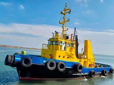
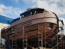
1995 Tug - Twin Screw For Sale $750,000
DO0339 Tug - Twin Screw For Sale
- FROM DIRECT OWNERS -
Accommodations 7
Deck Crane
Fire Fighting System... read more | Year: | 1995 |
| Length: | 27m |
| Location: | WCSA Ecuador |
| Price: | $750,000 |
View Details | |
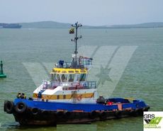
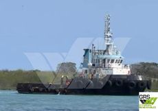
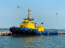
LOA 22,5 m
Beam 7,2 m
Draft 3,18 m
Bollard Pull : 31 tons
Speed : 11,4 knots
Engines : 2 x Cummins / Cummins Diesel International KTA-38-M, 1.560 kw, 1.950 rpm, Propellers 1 Fixed Pitch (Port Side) + 1 Fixed Pitch (Starboard)
Auxiliaries Engines : 2 Cummins 58 kw
Fire Fighting System installed
Built in year 1996
Design is : Damen ST 2207
Class : Lloyd's Register
Flag : Colombia
Gross Tonnage of 135 and Nett Tonnage of 40
Deadweight : 90 metric tonnes... read more
| Year: | 1996 |
| Length: | 22.5m |
| Location: | Hamburg Hamburg Germany |
View Details | |

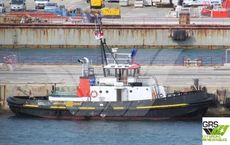
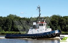
LOA 21,8 m
Beam 7 m
Bollard Pull : 12 tons
Speed : 10,8 knots
Engines : 2 x Poyaud A12, 854 kw, 150 rpm
Auxiliaries Engines : 2 x 5 kw
Capable of supplies of 31m³ Fuel Oils and 18m³ FW
Built in year 1978
Class : Bureau Veritas
Flag : Monaco
Gross Tonnage of 91... read more
| Year: | 1978 |
| Length: | 21.8m |
| Location: | Hamburg Hamburg Germany |
| Price: | €370,000 |
View Details | |
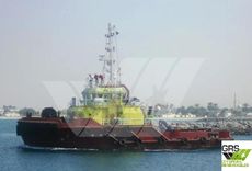
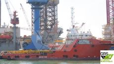
LOA 31,02 m
Beam 11 m
Draft 4,6 m
Bollard Pull : 72 tons
Speed : 12,5 knots
Engines : 2 x Caterpillar / Caterpillar Inc 3516B-HD, 3.840 kw, 1.600 rpm, Propellers 1 Z Type (Port Side) + 1 Z Type (Starboard)
Auxiliaries Engines : 2 Cummins 164 kw, Bowthruster + No Sternthruster (1 Bow Tunnel thruster 184kw)
Fire Fighting System of type FiFi 1 installed
Built in year 2009
Class : Lloyd's Register
Flag : Virgin Islands (British)
Gross Tonnage of 478 and Nett Tonnage of 136... read more
| Year: | 2009 |
| Length: | 31.02m |
| Location: | Hamburg Hamburg Germany |
View Details | |
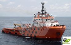
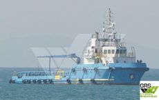
LOA 41,8 m
Beam 10 m
Draft 3,2 m
Built in year 2009
Design is : BluMarlin 41m
Class : Bureau Veritas
Flag : Indonesia
Gross Tonnage of 573 and Nett Tonnage of 174
Deadweight : 326 metric tonnes
Bollard Pull : 52 tons
Speed : 11 knots
Engines : 2 x Mitsubishi / Mitsubishi Heavy Industries S8U-MPTK, 2.984 kw, 1.100 rpm, Propellers 1 Fixed Pitch (Port Side) + 1 Fixed Pitch (Starboard)
Auxiliaries Engines : 3 Volvo Penta 235 kw, Bowthruster + No Sternthruster (1 Bow Tunnel thruster 350kw)
1 Deck... read more
| Year: | 2009 |
| Length: | 41.8m |
| Location: | Hamburg Hamburg Germany |
View Details | |
LOA 32 m
Beam 9,14 m
Draft 3,5 m
Speed : 10 knots
Engines : 2 x Cummins / Cummins Engine Co Inc KTA-50-M2, 2.682 kw, 1.800 rpm, Propellers 1 Fixed Pitch (Port Side) + 1 Fixed Pitch (Starboard)
Auxiliaries Engines : 2 Cummins 128 kw
Built in year 2007
Class : Registro Italiano Navale
Flag : Mexico
Gross Tonnage of 296 and Nett Tonnage of 88
Deadweight : 227 metric tonnes... read more
| Year: | 2007 |
| Length: | 32m |
| Location: | Hamburg Hamburg Germany |
View Details | |
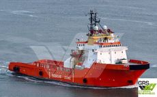
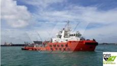
Featured in GRS Newsletter August 2015 80m / DP 1 / 156ts BP AHTS Vessel for Sale / #1029976 $2,600,000
LOA 79,7 m
Beam 18 m
Draft 5,95 m
Bollard Pull : 156 tons
Dynamic Positioning of class : DP 1
Free Deck area about 570m²
Capable of supplies of 961m³ Fuel Oils, 164m³ Methanol, 611m³ FW, 640m³ Liquid Mud and 395m³ Brine
Fire Fighting System of type FiFi 2 installed
1 Crane / Gear installed with a max lifting capacity of 5 tons
1 Crane / Gear installed with a max lifting capacity of 1,5 tons
Built in year 1986
Design is : UT 716
Class : Bureau Veritas
Flag : Liberia
Gross Tonnage of 1.741 and Nett Tonnage of 944
Deadweight : 2.500 metric tonnes
Total 20 berths
8 cabins with 1 b... read more | Year: | 1986 |
| Length: | 79.7m |
| Location: | Hamburg Hamburg Germany |
| Price: | $2,600,000 |
View Details | |
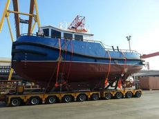
DIMENSIONS
Length OA 15,00 m
Beam OA 5,80 m
Depth at sides 2,40 m
Draught Aft 1,60 m
TANK CAPACITIES
Fuel-Oil 11,52 m3
Fresh Water 2,15 m3
Sawage 1,60 m3... read more
| Year: | 2023 |
| Length: | 15' 20" |
| Location: | Turkey |
View Details | |
17.00m x 7.70m x 2.95m "MULTIPURPOSE TUGBOAT 1708" Tugboat
Built 2020 in Turkey
Basic functions: Towing, survey, anchor handling, dredge & coastal construction support
Class : Bureau Veritas
M/E : 2 x CaterpillarC18 engines - total 1640 bhp at 2200 rpm
Speed: 10.5 knots
TBP : 19
Bowthruster : 1 x 120 hp (optional)
Propulsion : 2 x Kaplan Type fixed pitch propellers
Generator sets: 2 x Hz 30KVA, 50HZ
Fuel oil capacity: 20.00 m3
Fresh water capacity: 13.90 m3
Lube oil capacity: 2.0 m3
Deck crane : 10 T/m
Towing winch : 40 ton @ 6 m/min (optional)
Towing pins ... read more
| Year: | 2020 |
| Length: | 17m |
| Location: | Norway |
View Details | |
2007 Tug - Twin Screw For Sale $1,900,000
DO0305 Tug - Twin Screw For Sale
- FROM DIRECT OWNERS -
Reported to be in excellent condition. Currently operating.
Dry docked recently with main engines and gearboxes overhauled.
Water Ballast 14 m3... read more | Year: | 2007 |
| Length: | 32m |
| Location: | COLOMBIA PACIFIC Colombia |
| Price: | $1,900,000 |
View Details | |
LOA 24,31 m
Beam 7,31 m
Draft 3,19 m
Bollard Pull : 30 tons
Speed : 10,5 knots
Engines : 2 x Ruston / Ruston Diesels Ltd 6AP230M, 1.389 kw, 750 rpm, Propellers 1 Fixed Pitch (Port Side) + 1 Fixed Pitch (Starboard)
Auxiliaries Engines : 2 Volvo Penta 80 kw
Capable of supplies of 61m³ Fuel Oils and 18m³ FW
Built in year 1988
Class : Lloyd's Register
Flag : Netherlands
Gross Tonnage of 156 and Nett Tonnage of 46
Deadweight : 89 metric tonnes... read more
| Year: | 1988 |
| Length: | 24.31m |
| Location: | Hamburg Hamburg Germany |
| Price: | €850,000 |
View Details | |
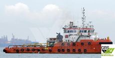
LOA 59,85 m
Beam 14,95 m
Draft 4,75 m
Bollard Pull : 75 tons
Dynamic Positioning of class : DP 1
Free Deck area about 330m² with a deck strength of 7 metric tonnes per square meter
Fire Fighting System of type FiFi 1 installed
Built in year 2015
Design is : DN59M
Class : American Bureau of Shipping
Flag : Singapore
Gross Tonnage of 1.714 and Nett Tonnage of 514
Deadweight : 1.486 metric tonnes
Engines : 2 x Caterpillar / Caterpillar Inc 3516C-HD, 4.480 kw, 1.800 rpm, Propellers 1 Controllable Pitch (Port Side) + 1 Controllable Pitch (Starboard)
Auxiliaries Engines : 2 Caterpillar ... read more
| Year: | 2015 |
| Length: | 59.85m |
| Location: | Hamburg Hamburg Germany |
| Price: | $10,000,000 |
View Details | |
LOA 45 m
Beam 12,6 m
Draft 4,5 m
Built in year 2012
Class : American Bureau of Shipping
Flag : Singapore
Gross Tonnage of 883 and Nett Tonnage of 265
Deadweight : 547 metric tonnes
Bollard Pull : 71 tons
Fire Fighting System installed
1 Crane / Gear installed with a max lifting capacity of 1 tons
Total 22 berths
6 cabins with 1 berth
8 cabins with 2 berths
Speed : 10 knots
Engines : 2 x Caterpillar / Caterpillar Inc 3516B-HD, 3.787 kw, 1.600 rpm, Propellers 1 Fixed Pitch (Port Side) + 1 Fixed Pitch (Starboard)
Auxiliaries Engines : 1 Cummins 390 kw + 2 Cummins 180 kw, Bowthruster... read more
| Year: | 2012 |
| Length: | 45m |
| Location: | Hamburg Hamburg Germany |
| Price: | $5,800,000 |
View Details | |
LOA 65,5 m
Beam 16 m
Draft 5,8 m
Bollard Pull : 110 tons
Dynamic Positioning of class : DP 1
Free Deck area about 415m²
Fire Fighting System of type FiFi 1 installed
Built in year 2009
Design is : Armada-8000
Class : China Classification Society
Flag : China
Gross Tonnage of 2.147 and Nett Tonnage of 644
Deadweight : 2.067 metric tonnes
Engines : 2 x Bergens / Rolls-Royce Marine AS B32:40L6P, 6.000 kw, 750 rpm, Propellers 1 Controllable Pitch (Port Side) + 1 Controllable Pitch (Starboard)
Auxiliaries Engines : 2 Cummins 485 kw... read more
| Year: | 2009 |
| Length: | 65.5m |
| Location: | Hamburg Hamburg Germany |
View Details | |
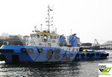
30m / 44ts BP Tug for Sale / #1074064 €1,300,000
LOA 30,2 m
Beam 9 m
Draft 3,81 m
Bollard Pull : 44 tons
Speed : 11 knots
Engines : 2 x Cummins / Cummins Engine Co Ltd KTA-38-M2, 1.780 kw, 1.800 rpm, Propellers 1 x Port Side + 1 x Starboard
Auxiliaries Engines : 1 Cummins 112 kw
Built in year 2011
Flag : Comoro
Gross Tonnage of 281 and Nett Tonnage of 85
Deadweight : 295 metric tonnes... read more | Year: | 2011 |
| Length: | 30.2m |
| Location: | Hamburg Hamburg Germany |
| Price: | €1,300,000 |
View Details | |
LOA 45 m
Beam 11,8 m
Draft 3,8 m
Bollard Pull : 46 tons
Fire Fighting System installed
Built in year 2007
Design is : KCM 45M
Class : Bureau Veritas
Flag : Malaysia
Gross Tonnage of 641 and Nett Tonnage of 192
Deadweight : 576 metric tonnes
Total passenger capacity 20 with 20 berths
Speed : 9 knots
Engines : 2 x Caterpillar / Caterpillar Inc 3512B, 2.850 kw, 1.600 rpm, Propellers 1 Fixed Pitch (Port Side) + 1 Fixed Pitch (Starboard)
Auxiliaries Engines : 3 Caterpillar 140 kw, Bowthruster + No Sternthruster (1 Bow Tunnel thruster)... read more
| Year: | 2007 |
| Length: | 45m |
| Location: | Hamburg Hamburg Germany |
View Details | |
An English Steel Tug , Ideal for Construction works
GRT 265,81
NRT 50,40
LOA 38,86 M
BEAM 8,72 M
DRAFT 3,32 M... read more
| Year: | 1970 |
| Length: | 38.86m |
| Location: | Aegean Islands Greece |
View Details | |

Ex Naval Tug, Irene. Currently working on Tidal Thames For Sale.
Irene has AIS, Navigation equipment, Radar 2x VHF radios.
Toilet and black water tank. Galley fitted with oven, microwave and sink.... read more
| Year: | 1960 |
| Length: | 19m |
| Location: | London UK |
View Details | |
We are pleased to present for sale this 23m 31t Bollard Pull Twin Screw Damen tug.
This vessel has a bollard pull of 31t and a towing winch.
There is accommodation on board for up to 6 people and an aft working area of 35sqm.
Available in the Caribbean Sea, please get in touch for further pricing and availability.
All details presented in good faith but without guarantee.... read more
| Year: | 1996 |
| Length: | 22.50m |
| Location: | CARIBBEAN SOUTH AMERICA UK |
View Details | |

DO0338 Tug - Twin Screw For Charter
- FROM DIRECT OWNERS -
Speed and consumption:10 knots @ 4 m cub/ 24h
Fuel grade: MGO... read more
| Length: | 22.50m |
| Location: | WEST MED Spain |
View Details | |